Networking: Ethernet Frames

What is Ethernet? This is a question that cybersecurity professionals should be able to answer. It is the basic building block of network models and how packets start to transit from Host A to Host B. This post will discuss some of the characteristics of Ethernet frames in general.
To start, let's examine output from a packet capture:
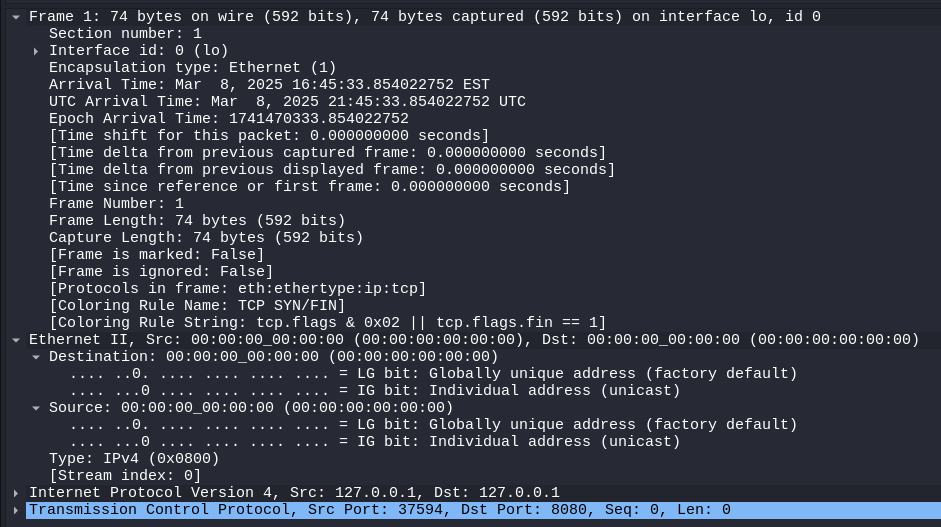
We are going to focus on analyzing the first two sections: Frame and Ethernet II. In the Frame section, we can see that this capture was completed on the lo interface, this packet is 74 bytes in total, and the next protocol is Ethernet. Note that Ethernet is the dominant data link layer protocol today, however there are others out there like IEEE 802.11 (WiFi), MPLS, Token Ring, and STP.
Within the Ethernet section of this packet (or frame), we see the source MAC address, destination MAC address, and indication that the next protocol is IPv4 (type 0x0800). Similarly, IPv4 is one of the dominant Internet protocols however there are many more. In this example, the source and destination MAC address is set to 00:00:00:00:00:00 because this was a capture on localhost; the packet originated from this machine and never left this machine. Every network interface card (NIC) has a unique MAC address within a local area network (LAN). This includes WiFi and wired interfaces. If uniqueness is not maintained within the LAN, collisions and packet loss will occur as computers become confused about where a packet should be delivered. In a simple home network with multiple user devices and a single router, most packets will have a source MAC address from your computer and a destination MAC address of your router. Both MAC addresses get rewritten by routing devices as the packet traverses the internet to its destination.
MAC Addressing
MAC addresses are 6 bytes long and contain values from 0x00 through 0xFF in each position. There are some reserved MAC addresses for broadcast and multicast packets. The first 3 bytes in a MAC address represent the "OUI". These are mapped to specific network interface vendors. The last 3 bytes are the host identifier.
Framing
All network communications start as a Frame from layer 1 to layer 2. Once IP addresses and applications get added to the Frame, the data becomes a Packet. This is an important distinction when describing a network. The maximum frame size is 1518 bytes, however jumbo frames are usually allowed in modern switched networks. The minimum frame size is 64 bytes for comatibility with older devices. Some protocols, such as ARP, need to use padding bytes to reach this minimum size.
Ethernet II is the modern framing standard. The format is as follows:
Destination MAC (6 bytes) | Source MAC (6 bytes) | Type (2 bytes) | Data (46 - 1500 bytes) | CRC Checksum (4 bytes)
The Ethernet type defines the payload within the frame. Some common type values are 0x0800 (IPv4), 0x0806 (ARP), 0x8035 (RARP), 0x8100 (802.1Q VLAN tagging), and 0x86DD (IPv6).
The CRC checksum is used for error detection in networking. If the CRC does not match what it should be based on the rest of the frame data, then the packet is discarded with no further action taken. Other upper level protocols, such as TCP, may handle the checksum error nicely but Ethernet does not. Common causes of checksum errors include collisions and electrical interference.
Unicast, Multicast, and Broadcast
These terms indicate how many recipients a frame is destined for. A frame can be unicast (one to one), multicast (one to many), or broadcast (one to all). Multicast MAC addresses do not contain an OUI. Some common multicast addresses are 01:00:0c:cc:cc:cc for Cisco Discovery Protocol (CDP) or 01:80:c2:00:00:00 for Spanning Tree Protocol (STP). Broadcast frames reach all hosts within a LAN. They have a destination MAC address of ff:ff:ff:ff:ff:ff and also do not contain an OUI. This type of frame is often used for ARP and DHCP.
Frame Domains and Virtual LANs (VLAN)
A frame domain, or broadcast domain, is a logical separation of networks. This type of separation is common on modern networks but it didn't used to be. Separation of domains causes less frame collisions and limits some network attacks such as broadcast storms. With traditional ethernet bus topology, there was a shared transfer medium between all hosts (i.e. a single ethernet cable). This creates 1 collision domain and vastly increases the chance of errors. On modern switched networks, every port on the switch is its own collision domain. When the port is only used between the switch and an endpoint device, the risk of collisions is virtually zero.
Regarding broadcast frames, all machines within a LAN share the same broadcast domain. This means that broadcast frames will be transmitted to all other hosts on the LAN...and only the LAN. Routers do not forward broadcast frames to other networks under most conditions. This can be configured for cross-network DHCP or other use cases. This is why protocols such as ARP, DHCP, or NetBIOS only contain information for the current LAN and nothing from other networks. Domains are all about network segmentation.
VLANs are another method of adding additional network segmentation without additional hardware investment. At a basic level, VLANs allow a single switch to act like several physical switches and creating multiple broadcast domains. Packets that need to move between VLANs need to be routed and therefore will be tagged with an associated VLAN number. Furthermore, since routing needs to occur, broadcast frames will not transit between VLANs.